tech
Driveline Angles
Article
written by Drivetrain Doctors
www.drivetrain.com - we help you solve the problem!
The u-joint operating angle is the angle
formed by two yokes connected by a cross and bearing kit.
There are two kinds of u-joint angles.
The simple one plane angle found in most
installations has all driveline slope confined to one plane,
usually the vertical plane. The other type of driveline
angle is compound angle in two planes. This is found in
driveline designs where offset exists in both the vertical
and horizontal planes.
|
|
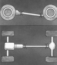
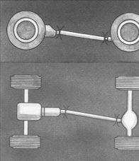
One Plane Angle
Driveshafts, Side & Top View |
Two Plane Angle
Driveshaft, Side & Top View |
High angles combined with high RPM is the
worst combination, resulting in reduced u-joint life. Too
large and unequal u-joint angles can cause vibrations and
contribute to u-joint, transmission and differential
problems. The improper u-joint angles must be corrected.
Ideally, the operating angles on each end
of the driveshaft should be equal to or within 1 degree of
each other, have a 3 degree maximum operating angle and have
at least 1/2 of a degree continuous operating angle.
RPM is the main factor though in
determining maximum allowable operating angles. As a guide
to maximum normal operating angles, refer to the following
chart:
DRIVESHAFT RPM
|
MAX. NORMAL
OPERATING ANGLE |
5000 |
3.25º |
4500 |
3.67º |
4000 |
4.25º |
3500 |
5.00º |
3000 |
5.83º |
2500 |
7.00º |
2000 |
8.67º |
1500 |
11.5º |
When the transmission output shaft
centerline and axle input shaft centerline are parallel, the
u-joint operating angle permissible is length of driveshaft
divided by five. Example: A short coupled driveshaft with a
15" length would be limited to 3 degrees maximum operating
angle. A 30" shaft would be limited to 6 degrees.
When the transmission output shaft
centerline and axle input shaft centerline intersect midway
of the driveshaft, the joint angles are equal. However, due
to the change to unequal joint angles during up and down
axle movement, this is a more undesirable condition than
parallel centerlines. In this case, the maximum u-joint
operating angle is determined by dividing length of
driveshaft by ten. Example: A 30" driveshaft with
intersecting angles would have a 3 degree permissible
operating angle.
CHECKING DRIVESHAFT ANGLES IN THE
VERTICAL OR HORIZONTAL PLANE
WARNING:
|
Rotating shafts can
be dangerous. You can snag clothes, skin, hair,
hands, etc. This can cause serious injury or death.
Do not work on a shaft (with or without a guard)
when the engine is running |
Use the following procedure to check
driveshaft angles for proper u-joint operating angles.
1. Inflate all tires to the pressure at
which they are normally operated. Park the vehicle on a
surface which is as level as possible both from front to
rear and from side to side. Do not attempt to level the
vehicle by jacking up the front or rear axles. Shift the
transmission into neutral and block the front tires. Jack up
a rear wheel.
2. Rotate the wheel by hand until the
output yoke on the transmission is vertical, and lower the
jack. This simplifies measurement later. Check driveshaft
angles in the same loaded or unloaded condition as when the
vibrations or noise occurred. Always try to check driveline
angles in both loaded and unloaded conditions.
3. To determine driveshaft angles, a
spirit level protractor or Spicer Anglemaster ® II
Electronic Driveline
Inclinometer
is required. On a protractor, when angles are read from 0
degree mark (horizontally - on the driveshaft) record and
use the angle shown. When angles are read from either of the
90 degree marks (vertically - on the flange) do not record
the angle shown on the protractor since the 90 degree marks
must be understood to be the same as 0 degrees on the
horizontal plane. Thus, if a vertical reading is 85 degrees,
the angle being measured is 5 degrees (90 - 85 = 5 degrees).
To use the Spicer Anglemaster ® II
Electronic Driveline Inclinometer, simply place the sensor
on the component to be measured. A display module will show
what the angle is and in which direction it slopes. We offer
Spicer Anglemaster ® II Electronic Driveline Inclinometer
for $300.00.
If using a protractor, all angles should
be read within 0.25 degree and they should be measured with
the
protractor
held plumb on a clean flat surface. The Spicer Anglemaster ®
II Electronic Driveline Inclinometer is automatically
accurate to within 1/10 of 1 degree. Always measure the
slope of the drivetrain going from front to rear. A
component slopes downward if it is lower at the rear than
the front. A component slopes upward when it is higher at
the rear than it is in front.
4. Check and record the angle on the main
transmission. This reading can be taken on the end yoke lug,
with the bearing assembly removed or on a flat surface of
the main transmission parallel or perpendicular to the
output yoke lug plane. Record your readings on a sketch.
5. Now check the drive shaft angle between
the transmission and axle or forward axle. On short tube
length driveshafts, check the angle of the driveshaft on
either the tube or slip yoke lug with the bearing assembly
removed. On long tube length driveshafts, measure the angle
on the tube at least 3" away from the circle welds or at
least 1" away from any balance weights. Be sure to remove
any rust, scale or sound deadening compounds from the tube
to obtain an accurate measurement.
6. Check the forward axle input yoke angle by removing a
bearing assembly and measuring the angle on the yoke lugs or
on a flat surface of the angle housing parallel or
perpendicular to the input yoke lug plane.
7. If applicable, measure the output yoke angle of the
forward axle, the angle of the tandem driveshaft between the
forward axle and the rear axle, and the rear axle input yoke
angle.
With all of the angles recorded, complete
a drawing as shown below. There are no u-joint operating
angles in your drawing at this time, jut the slope of the
components and their direction. To determine u-joint
operating angles, simply find the difference in the slopes
of the components.
When the slopes are in the Same
direction on two connected components, Subtract the
smaller number from the larger to find the u-joint operating
angle. When the slopes are in the Opposite direction
on two connected components, Add the measurements to
find the u-joint operating angle.
Now compare the u-joint operating angles
on your drawing to the rules for ideal operating angles
mentioned above.
CORRECTING U-JOINT OPERATING ANGLES
The recommended method for correcting
severe u-joint operating angles depends on the vehicle
suspension or driveline design. On vehicles with leaf
springs suspension, thin wedges called axle shims can be
installed
under
the leaf springs of single axle vehicles to tilt the axle
and correct u-joint operating angles. Wedges are available
in a range of sizes to change pinion angles. On vehicles
with tandem axles, the torque rods can be shimmed. Torque
rod shims rotate the axle pinion to change the u-joint
operating angle. A longer or shorter torque rod may be
available from the manufacture if shimming is not practical.
Some torque rods are adjustable.
As a general rule, the addition or removal
of a 1/4" shim from the rear torque arm will change the axle
angle approximately 3/4 of a degree. A 3/4 of a degree
change in the pinion angle will change the u-joint operating
angle about 1/4 of a degree.
Always take the time to call the vehicle
manufacturer if there are unusual u-joint operating angle
problems.
WHAT CAUSES U-JOINT OPERATING ANGLES TO
CHANGE
- Suspension changes caused by: worn
bushings in the spring hangers, worn bushings in the
torque rods incorrect airbag height
- Revisions in components of the
driveline
- Stretching or shortening the chassis
- Adding an auxiliary transmission or
transfer case in the main driveline
- Worn engine mounts
- Raising or lowering of the vehicle
DRIVESHAFT BRAKE
When a driveshaft brake is used, care must
be taken to see that the brake drum is properly piloted,
runs true and is in balance.
Visit Drivetrain
Specialists at
www.drivetrain.com or you can call the order
desk at 1-800-216-1632 to talk to a knowledgeable
technician. If you are considering purchasing
parts from drivetrain.com and have questions contact the
Tech line at 1-702-876-3100 or send
e-mail.
Drivetrain Specialists of Las Vegas - Las Vegas NV, 89102
|